Design Analysis of LED Lamp Inner Shells Based on UG or MFI
Bicycle LED lights are an important guarantee for the safety of cyclists at night. The inner shell for fixing the LED components is the core part of the lamp and is usually made of the ABS plastic by injection molding. The plastic parts of the inner shell usually have complex structure because they undertake the role of structural support and internal and external connection; they have a small overall volume and require high precision. The corresponding injection mold for the molded plastic part is also very complex; the molding is difficult, and there are many core-pulling parts. Therefore, in the process of mold design, the molding process of plastic parts and the manufacturing process of the mold should be fully considered to ensure the manufacturing accuracy of the mold and the requirements of the product.
1. The structure of the plastic
Figure 1 and Figure 2 are the outline of the bicycle LED light and the structure of the inner shell. Its output is 25,000 pieces. The maximum external dimension of the plastic part is 105 mm × 63 mm × 21 mm, the wall thickness 1.85 mm, the volume 13.3 cm3, and the mass 0.014kg. As shown in Figure 2b, the plastic part has a small structure and is curved inward as a whole. It also has the following features: (1) There are some characters on the front that identifies specifications and installation directions of batteries. (2) There is a process undercut structure next to the character to avoid shrinkage holes in the injection molding. (3) In addition to the side concave structure, each has a protruding outer buckle.
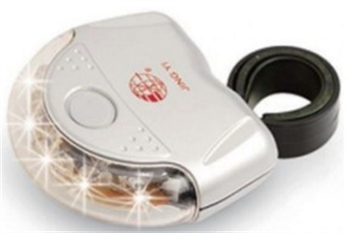
Figure 1 Bicycle LED taillights
⑷The middle is the slot for placing the electronic circuit board. ⑸ There is a hole in the middle for wiring through the circuit board and the LED lamp bead. ⑹There are battery slots and side buttons for placing batteries inside the casing. ⑺There is an inner buckle for clamping the circuit board. To operate the inner buckle, there are 2 long holes in the corresponding position at the back. ⑻ There is another outer button in the middle of the long hole.
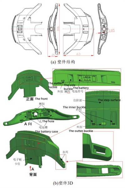
Figure 2 LED light inner shell plastic parts
(a) The structure of the plastic part (b) The 3D plastic part
2. Design analyses
2.1 The layout of the cavity
From the structure and requirements of the inner shell of the LED lamp: (1) One-mold two-cavity injection molding can be used due to the small size of the product and the large output. (2) The plastic parts can be arranged in the mold according to the direction of normal viewing of the logo font as shown in Figure 2b so as to achieve the following two aspects. The first is to use the movable and fixed molds to open the mold with a large opening stroke, and complete core-pull forming of deep cavity structure in a vertical direction of the battery slot, electronic board card position and hole. The second is that the lateral parting and core-pulling mechanism can be used to perform core-pulling separation with the help of the demoulding force provided by the demoulding device of the injection machine for structures with small shapes and sizes such as concave-convex characters, side concave, external buckles, and long holes on the outside of plastic parts. (3) Comprehensively considering the cavity layout, pouring and demoulding, a special flow channel with one mold and two cavities is designed for this mold, and after multiple mold flow analyses, it is proposed that the flow channel plus plastic parts are used as the layout for the mold of injection molded parts, as shown in Figure 3. After the inner shell of the LED lamp is demolded and the injection molded product is taken out, the gate is cut off.
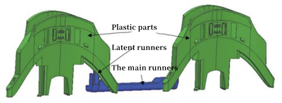
Figure 3 The layout of the main runner and cavity
2.2 The analysis of the mold flow
Use Moldflow CAD Doctor 2015 to simplify the inner shell plus runner model shown in Figure 3 to remove small rounded corners, chamfers, and small step surfaces. The simplified model will not affect the results of mold flow analysis of plastic products, and import the adjusted 3D model into MFI2015. In order to improve the quality and accuracy of the grid for analysis, a double-layer grid is used for division, and the grid length is 2mm. After division, defects such as free edges, intersecting elements, and aspect ratios are repaired. The final mesh is as follows: 64,532 triangular mesh elements, 85.9% matching percentage, 86.1% mutual percentage, maximum aspect ratio 57.12, average aspect ratio 2.63, with a minimum aspect ratio of 1.16. The above mesh quality can complete the molding flow analysis of the plastic parts to study the filling pressure, filling time, cooling time and product warpage during injection so as to provide a basis for the next step in the mold structure design.
Figure 4 shows the results of the mold flow analysis. Since the product adopts the form of one mold and two cavities, it can be seen from Figure 4a that it is most suitable for the gate of the injection molded product to be located in the geometric center of the main runner. The simulation results show that the filling time is 0.8758 seconds from Figure 4b. It can be seen from Figure 4c that the filling pressure at the far end of the lamp housing is the smallest, mainly because the distance is long and the plastic flow pressure loss is great. However, it can still be filled fully. It can be seen from Figure 4d that air pockets appear on the end faces or corners of the lamp housing. For the design of this mold, it is necessary to use a large number of structures such as combined cores and inserts, and the use of their gaps can solve the exhaust gas well and reduce air pockets. It can be seen from 4e that the overall deformation of the product of the plastic part plus runner is 1.187mm, ignoring the effect of deformation on the runner, the deformation of the lamp housing is less than 0.8364mm. In summary, the product filling quality is guaranteed and can meet the design requirements.
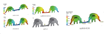
(a) The analysis of the pouring gate (b) Filling time (c) Filling end pressure (d) Air pockets (e) Comprehensive deformation
Figure 4 Mold flow analysis results
Figure 1 Bicycle LED taillights
⑷The middle is the slot for placing the electronic circuit board. ⑸ There is a hole in the middle for wiring through the circuit board and the LED lamp bead. ⑹There are battery slots and side buttons for placing batteries inside the casing. ⑺There is an inner buckle for clamping the circuit board. To operate the inner buckle, there are 2 long holes in the corresponding position at the back. ⑻ There is another outer button in the middle of the long hole.
Figure 2 LED light inner shell plastic parts
(a) The structure of the plastic part (b) The 3D plastic part
2. Design analyses
2.1 The layout of the cavity
From the structure and requirements of the inner shell of the LED lamp: (1) One-mold two-cavity injection molding can be used due to the small size of the product and the large output. (2) The plastic parts can be arranged in the mold according to the direction of normal viewing of the logo font as shown in Figure 2b so as to achieve the following two aspects. The first is to use the movable and fixed molds to open the mold with a large opening stroke, and complete core-pull forming of deep cavity structure in a vertical direction of the battery slot, electronic board card position and hole. The second is that the lateral parting and core-pulling mechanism can be used to perform core-pulling separation with the help of the demoulding force provided by the demoulding device of the injection machine for structures with small shapes and sizes such as concave-convex characters, side concave, external buckles, and long holes on the outside of plastic parts. (3) Comprehensively considering the cavity layout, pouring and demoulding, a special flow channel with one mold and two cavities is designed for this mold, and after multiple mold flow analyses, it is proposed that the flow channel plus plastic parts are used as the layout for the mold of injection molded parts, as shown in Figure 3. After the inner shell of the LED lamp is demolded and the injection molded product is taken out, the gate is cut off.
Figure 3 The layout of the main runner and cavity
2.2 The analysis of the mold flow
Use Moldflow CAD Doctor 2015 to simplify the inner shell plus runner model shown in Figure 3 to remove small rounded corners, chamfers, and small step surfaces. The simplified model will not affect the results of mold flow analysis of plastic products, and import the adjusted 3D model into MFI2015. In order to improve the quality and accuracy of the grid for analysis, a double-layer grid is used for division, and the grid length is 2mm. After division, defects such as free edges, intersecting elements, and aspect ratios are repaired. The final mesh is as follows: 64,532 triangular mesh elements, 85.9% matching percentage, 86.1% mutual percentage, maximum aspect ratio 57.12, average aspect ratio 2.63, with a minimum aspect ratio of 1.16. The above mesh quality can complete the molding flow analysis of the plastic parts to study the filling pressure, filling time, cooling time and product warpage during injection so as to provide a basis for the next step in the mold structure design.
Figure 4 shows the results of the mold flow analysis. Since the product adopts the form of one mold and two cavities, it can be seen from Figure 4a that it is most suitable for the gate of the injection molded product to be located in the geometric center of the main runner. The simulation results show that the filling time is 0.8758 seconds from Figure 4b. It can be seen from Figure 4c that the filling pressure at the far end of the lamp housing is the smallest, mainly because the distance is long and the plastic flow pressure loss is great. However, it can still be filled fully. It can be seen from Figure 4d that air pockets appear on the end faces or corners of the lamp housing. For the design of this mold, it is necessary to use a large number of structures such as combined cores and inserts, and the use of their gaps can solve the exhaust gas well and reduce air pockets. It can be seen from 4e that the overall deformation of the product of the plastic part plus runner is 1.187mm, ignoring the effect of deformation on the runner, the deformation of the lamp housing is less than 0.8364mm. In summary, the product filling quality is guaranteed and can meet the design requirements.
(a) The analysis of the pouring gate (b) Filling time (c) Filling end pressure (d) Air pockets (e) Comprehensive deformation
Figure 4 Mold flow analysis results

Related News
- Design of Two-stage Overmolding for Automobile Headlight Cover
- Research on Stamping of Complex Aerospace Sheet Metal Components (Part Two)
- Research on Stamping of Complex Aerospace Sheet Metal Components (Part one)
- Design of the Upper Cover of a Household Air Conditioner Remote Control
- The Mold Cavity of Overmolding Handheld Forehead Thermometer Casing
- Overmolding Handheld Forehead Thermometer Shells
- Defects of Overmolded Lampshades
- An Introduction to Overmolding
- Overmolding Lampshades For Car Headlights
- Deformation of Plastic Components
News
Advantages
Low Cost
Topper leverages an offshore plastic mold making plant with a lower cost structure in order to offer lower pricing than Topper's competitors.
High Quality
Quick Turnaround
Topper leverages an offshore plastic mold making plant with a lower cost structure in order to offer lower pricing than Topper's competitors.
High Quality
Topper is ISO 9001:2008 certified, and Topper processing quality systems ensure that your parts are the highest quality possible for your applications.
Quick Turnaround
Topper offers three different shipping methods, including next day air, to accommodate your timing and budget requirements.
Online Quotes
Topper interactive online quotation system provides instant quotes for plastic mold making, injection molding, CNC machining and die casting.
Online Quotes
Topper interactive online quotation system provides instant quotes for plastic mold making, injection molding, CNC machining and die casting.
Follow Us
Topper is a professional plastic mold manufacturer in China, our injection molding service covers all walks of life, including medical, electronics, auto parts, appliance, etc.
Contact Us
Topper Plastic Mold Co., Ltd.
Address: No. 879, Xiahe Road, Xiamen, Fujian, China
Tel: 0086-592-5819200
Email: [email protected]
Website: https://www.plastic-mold.com
Copyright © China Plastic Mold Co., Ltd. Robot Arm for Injection Molding. Privacy Policy | Terms of Service | Sitemap
Website Design & Support: jeawin.com