The Design of the Injection Mold for LED Lamp Inner Shells (Part One)
1. Mold Design
One mold, two cavities, and two-parting three-plate type plastic parts plus runner product structure are adopted, the designed mold assembly structure and 3D effect are shown in Figure 1.
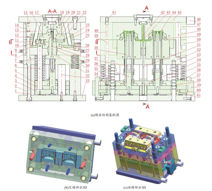
Figure 1 The structure and shape of the mold
(a) Assembly drawing of mold structure (b) 3D fixed mold parts (c) 3D movable mold parts
1. Screws 2. Support plates 3. Slot core fixing plates 4. Ejector plates 5. Ejector fixing plates 6. Distance rods 7. Return springs 8. Inlay 9. A1 antifriction pads 10. Dog plates 11. Oblique slider A 12. Anti-friction pad A2 13. Oblique guide post A 14. Guide sleeves 15. Guide posts 16. Side core A 17. Gate sleeves 18. Main runners 19. Main cavities 20. Position inserts 21. Side core B 22. Oblique guide post B 23. Oblique slider B 24. Anti-friction pad B2 25. Guide sliders 26. Antifriction pad B1 27. Cooling distribution plates 28. Core rods 29. Antifriction inserts 30. Springs of mold opening 31. Main cores 32. Support columns 33. Movable die bottom plates 34. Inlay sleeves 35. Limiting guide blocks 36. T-type sliding support 37. Battery groove cores 38. Ejector rods 39. Return rods 40. Return push rods 41. Return springs 42. Main runner condensate 43. Split runner condensate 44 Plastic parts 45. Fixed die bottom plates 46. Support die column 47. Fixed mold plates 48. Small guide column 49. T type panel 50. Movable templates 51. Pulling rods 52. Main core fixing plates 53. Extruding guide column 54. Adjusting screws 55. Limiting column 56. Limiting blocks 57. Limiting distance slanted blocks 58. Ejector guide sleeve A 59. Distance limit hooks 60. Retraction blocks 61. Ejector guide sleeves
Please note that there are a large number of left and right symmetrical parts with the same function in the mold. Annotate as necessary for the discussion for better expression.
1.1 The structure design of the cavity
Figure 2 shows the structure of the cavity. The cavity structural components are mainly composed of side core A16, main cavities, clamping insert, side core B21, insert 62, and T-shaped insert 63. The back side of the inner shell plastic part is formed on the side core A16. The protruding snap-in insert is close to the main core to form the electronic board on the back of the plastic part. The splicing of the cavity structure can not only solve the problems of forming the plastic part structure and difficult processing of the mold, but also can use the splicing gap to strengthen the exhaust of the mold.
Working principles: In the opening process of the mold, the movable mold part moves downward (as shown in Figure 1a), and the main cavity begins to separate from the plastic part. At the same time, the inclined guide post A13 and the inclined guide post B22 pass through the inclined slider A11 and B23 drive the side core A16, the side core B21 and other cavity components that are fastened together to be separated to the left and right together to realize the parting of the cavity and form the outer surface of the plastic part.
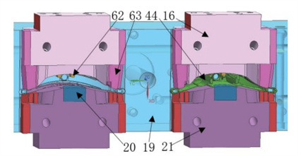
16. Side core A 19. Main cavities 20. Position inserts 21. Side cores B 44. Plastic parts 62. Inserts 63. T inserts
Figure 2 The structure of the cavity
1.2 The design of the core structure
Figure 3 shows the mold core structure. The core structural components are mainly composed of a clamping insert, an anti-friction insert, a battery groove core, an insert, and a main core. After being released from the plastic part, the inner surface of the plastic part is formed. The anti-friction insert is inserted into the main core with a transition fit with a small clearance. Similarly, the inlaid core structure can also solve the problems of structural molding of plastic parts and difficult processing of the mold, and at the same time strengthen the exhaust of the mold.
Working principles: At the beginning of the mold opening (as shown in Figure 1a), under the action of the mold opening spring, the main core fixing plate moves downward with the main core, the support plate, and the movable mold bottom plate which are fastened to it, making the mold open. The main core begins to be separated from the plastic part. When the moving distance is 5mm, the elastic deformation of the mold opening spring ends. Driven by the injection motorized plate, the movable mold part continues to move downward to form the second mold opening. When the movable mold part continues to move downward for 5mm, the cavity structure part starts to be demolded. When the moving distance of the movable mold part is +45mm, the demoulding of the cavity structure parts is completed.
At this time, the ejector plate on the ejector mechanism begins to contact the ejector rod on the injection machine, so that the ejector mechanism and its passing limiter are in contact with each other. The slot core fixing plate coupled with the hook stops moving. When the movable mold part continues to move down +41mm, the plastic part, the battery groove core, and the ejector rod which are now integrated are completely released from the main core. The ejector mechanism and the groove core fixing plate separate. When the movable mold part continues to move down +20mm, the ejector rod completely ejects the plastic part from the battery slot core.
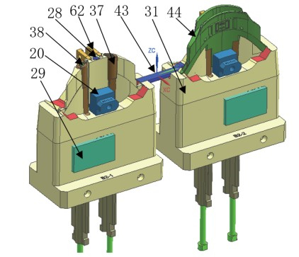
20. Position inserts 28. Core rods 29. Anti-friction inserts 31. Main cores 37. Battery groove cores 38. Ejector rods 43. Sub-runner condensate 44. Plastic parts 62. Inlays
Figure 3 The mold core structure
Figure 1 The structure and shape of the mold
(a) Assembly drawing of mold structure (b) 3D fixed mold parts (c) 3D movable mold parts
1. Screws 2. Support plates 3. Slot core fixing plates 4. Ejector plates 5. Ejector fixing plates 6. Distance rods 7. Return springs 8. Inlay 9. A1 antifriction pads 10. Dog plates 11. Oblique slider A 12. Anti-friction pad A2 13. Oblique guide post A 14. Guide sleeves 15. Guide posts 16. Side core A 17. Gate sleeves 18. Main runners 19. Main cavities 20. Position inserts 21. Side core B 22. Oblique guide post B 23. Oblique slider B 24. Anti-friction pad B2 25. Guide sliders 26. Antifriction pad B1 27. Cooling distribution plates 28. Core rods 29. Antifriction inserts 30. Springs of mold opening 31. Main cores 32. Support columns 33. Movable die bottom plates 34. Inlay sleeves 35. Limiting guide blocks 36. T-type sliding support 37. Battery groove cores 38. Ejector rods 39. Return rods 40. Return push rods 41. Return springs 42. Main runner condensate 43. Split runner condensate 44 Plastic parts 45. Fixed die bottom plates 46. Support die column 47. Fixed mold plates 48. Small guide column 49. T type panel 50. Movable templates 51. Pulling rods 52. Main core fixing plates 53. Extruding guide column 54. Adjusting screws 55. Limiting column 56. Limiting blocks 57. Limiting distance slanted blocks 58. Ejector guide sleeve A 59. Distance limit hooks 60. Retraction blocks 61. Ejector guide sleeves
Please note that there are a large number of left and right symmetrical parts with the same function in the mold. Annotate as necessary for the discussion for better expression.
1.1 The structure design of the cavity
Figure 2 shows the structure of the cavity. The cavity structural components are mainly composed of side core A16, main cavities, clamping insert, side core B21, insert 62, and T-shaped insert 63. The back side of the inner shell plastic part is formed on the side core A16. The protruding snap-in insert is close to the main core to form the electronic board on the back of the plastic part. The splicing of the cavity structure can not only solve the problems of forming the plastic part structure and difficult processing of the mold, but also can use the splicing gap to strengthen the exhaust of the mold.
Working principles: In the opening process of the mold, the movable mold part moves downward (as shown in Figure 1a), and the main cavity begins to separate from the plastic part. At the same time, the inclined guide post A13 and the inclined guide post B22 pass through the inclined slider A11 and B23 drive the side core A16, the side core B21 and other cavity components that are fastened together to be separated to the left and right together to realize the parting of the cavity and form the outer surface of the plastic part.
16. Side core A 19. Main cavities 20. Position inserts 21. Side cores B 44. Plastic parts 62. Inserts 63. T inserts
Figure 2 The structure of the cavity
1.2 The design of the core structure
Figure 3 shows the mold core structure. The core structural components are mainly composed of a clamping insert, an anti-friction insert, a battery groove core, an insert, and a main core. After being released from the plastic part, the inner surface of the plastic part is formed. The anti-friction insert is inserted into the main core with a transition fit with a small clearance. Similarly, the inlaid core structure can also solve the problems of structural molding of plastic parts and difficult processing of the mold, and at the same time strengthen the exhaust of the mold.
Working principles: At the beginning of the mold opening (as shown in Figure 1a), under the action of the mold opening spring, the main core fixing plate moves downward with the main core, the support plate, and the movable mold bottom plate which are fastened to it, making the mold open. The main core begins to be separated from the plastic part. When the moving distance is 5mm, the elastic deformation of the mold opening spring ends. Driven by the injection motorized plate, the movable mold part continues to move downward to form the second mold opening. When the movable mold part continues to move downward for 5mm, the cavity structure part starts to be demolded. When the moving distance of the movable mold part is +45mm, the demoulding of the cavity structure parts is completed.
At this time, the ejector plate on the ejector mechanism begins to contact the ejector rod on the injection machine, so that the ejector mechanism and its passing limiter are in contact with each other. The slot core fixing plate coupled with the hook stops moving. When the movable mold part continues to move down +41mm, the plastic part, the battery groove core, and the ejector rod which are now integrated are completely released from the main core. The ejector mechanism and the groove core fixing plate separate. When the movable mold part continues to move down +20mm, the ejector rod completely ejects the plastic part from the battery slot core.
20. Position inserts 28. Core rods 29. Anti-friction inserts 31. Main cores 37. Battery groove cores 38. Ejector rods 43. Sub-runner condensate 44. Plastic parts 62. Inlays
Figure 3 The mold core structure

Related News
- Design of Two-stage Overmolding for Automobile Headlight Cover
- Research on Stamping of Complex Aerospace Sheet Metal Components (Part Two)
- Research on Stamping of Complex Aerospace Sheet Metal Components (Part one)
- Design of the Upper Cover of a Household Air Conditioner Remote Control
- The Mold Cavity of Overmolding Handheld Forehead Thermometer Casing
- Overmolding Handheld Forehead Thermometer Shells
- Defects of Overmolded Lampshades
- An Introduction to Overmolding
- Overmolding Lampshades For Car Headlights
- Deformation of Plastic Components
News
Advantages
Low Cost
Topper leverages an offshore plastic mold making plant with a lower cost structure in order to offer lower pricing than Topper's competitors.
High Quality
Quick Turnaround
Topper leverages an offshore plastic mold making plant with a lower cost structure in order to offer lower pricing than Topper's competitors.
High Quality
Topper is ISO 9001:2008 certified, and Topper processing quality systems ensure that your parts are the highest quality possible for your applications.
Quick Turnaround
Topper offers three different shipping methods, including next day air, to accommodate your timing and budget requirements.
Online Quotes
Topper interactive online quotation system provides instant quotes for plastic mold making, injection molding, CNC machining and die casting.
Online Quotes
Topper interactive online quotation system provides instant quotes for plastic mold making, injection molding, CNC machining and die casting.
Follow Us
Topper is a professional plastic mold manufacturer in China, our injection molding service covers all walks of life, including medical, electronics, auto parts, appliance, etc.
Contact Us
Topper Plastic Mold Co., Ltd.
Address: No. 879, Xiahe Road, Xiamen, Fujian, China
Tel: 0086-592-5819200
Email: [email protected]
Website: https://www.plastic-mold.com
Copyright © China Plastic Mold Co., Ltd. Robot Arm for Injection Molding. Privacy Policy | Terms of Service | Sitemap
Website Design & Support: jeawin.com