The Importance of Locations of Pouring Gates
The pouring gate is the most critical part of the gating system, and its type and size are directly related to the quality of the product and the cost of the mold. There are many gate structures of injection molds, and different types of pouring gates have slightly different sizes, characteristics and applications. The shape, size and feeding position of the pouring gate have a great influence on the molding quality of plastic parts. Defects of plastic parts such as shrinkage, lack of materials, white spots, welding lines, brittleness, decomposition and warpage are often caused by unreasonable design of pouring gates. Therefore, correct design of the pouring gate is important to improve the quality of plastic parts.
The design of the pouring gate is related to factors such as properties of plastics, shapes of plastic parts, section sizes, mold structure and injection process parameters. The general requirement is to make the molten material enter and fill the cavity at a faster speed, and at the same time, it can be cooled and closed in time after filling. Therefore, the pouring gate section should be small and short, which can increase the material’s flow speed and quickly cool and seal, so that the plastic part is easy to be separated from the condensate of the pouring gate, leaving no obvious pouring gate marks, and ensuring the quality of appearance of the plastic parts.
The influence of the position of the pouring gate on the quality of injection molded products
The position of the pouring gate and shrinkage
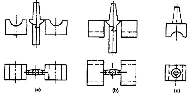
When the wall thickness of the plastic parts differs greatly, the pouring gate should be provided at the thickest part of the plastic part section in order to reduce the flow resistance and ensure that the plastic pressure is effectively transmitted to the thick-walled parts of the plastic parts to reduce shrinkage holes under the premise of avoiding spraying, which is conducive to filling supplements. If there are reinforcing ribs on the plastic parts, the reinforcing ribs can be used as flow channels to improve the flow conditions.
As shown in the figure below, if position a is selected for the pouring gate, the plastic part will have dents due to severe shrinkage. In Figure (b), the pouring gate is selected at the thick wall of the plastic part, which can overcome the dent. In Figure (c), the selection of a direct pouring gate greatly improves the filling conditions and improves the quality of plastic parts, but it will leave a great trace of de-gate.

Locations of pouring gates and discharging
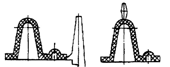
The location of the pouring gate should also be conducive to exhausting. Usually, the location of the pouring gate should be far away from the exhaust part. Otherwise, the plastic melt entering the cavity will close the exhaust system early, so that the gas in the cavity cannot be discharged smoothly, which will affect the molding quality of the plastic part, the location of the pouring gate as shown in the left of the following figure. When filling the mold, the melt will quickly close the exhaust gap at the parting surface of the mold, so that the gas in the cavity cannot be discharged, which will cause great filling resistance and easily form air bubbles, glue burning and other undesirable problems. If the position shown on the right in the figure below is used instead, such defects can be overcome, and the efficiency of the exhaust can be improved.

Locations of pouring gates and welding marks

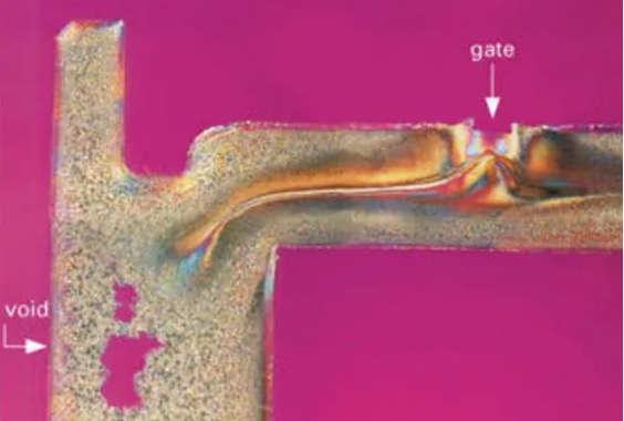
The determination of the position of the pouring gate not only determines the flow direction and flow balance of the polymer, but also plays an important role in the shape and pressure-holding effect of the melt flow front. The shape of the melt flow front can lead to welding lines and may affect the appearance of the plastic part.
Locations of pouring gates and shrinkages
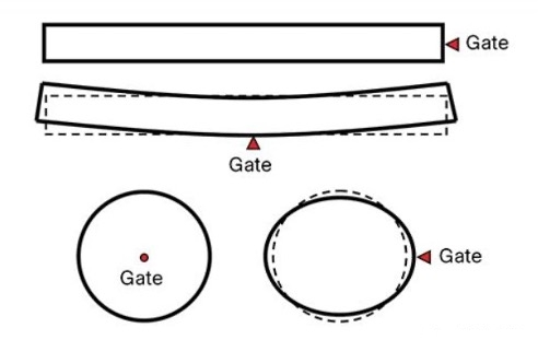
The setting of the position of pouring gates also considers the deformation and shrinkage of the plastic part. For crystalline plastics, the shrinkage rate in the plastic’s flow direction and the shrinkage perpendicular to the flow direction are very different, and the degree of deformation is also different when different forms of pouring gates are used. Of course, the number of pouring gates should also be considered, but sometimes the setting of the position of the pouring gate is more important than that of the number of pouring gates.

The location of the pouring gate affects the orientation of the polymer molecules and the shrinkage of the part. The image above shows that if a product is long and thin, and absolute straightness is required, then a pouring gate needs to be placed at the end of the product. The same is true for the guarantee of the roundness of round products, and the pouring gate needs to be set at the center of the circle, not the side.
Locations of pouring gates and appearance of plastic parts
The position of the pouring gate will always leave traces, so the pouring gate’s position should be set as far as possible in the parts that do not affect the appearance of the plastic part, such as the edge, bottom and inner side of the plastic part, especially for the plastic parts with high requirements for appearance.

Locations of pouring gates and plastic flows
When determining the pouring gate’s position of plastic parts, the maximum flow distance ratio allowed by the plastic, referred to as the flow ratio, should also be considered to ensure that the melt can fill the cavity. The maximum flow distance ratio refers to the ratio of the maximum length of the melt flowing in the cavity to the thickness of the runner. The allowable value of the flow ratio varies with properties of the melt, temperatures and injection pressure. If the calculated flow ratio is greater than the allowable value, it is necessary to increase the thickness of the product or change the pouring gate’s position or use multiple pouring gates to reduce the flow ratio.
Basic principles of designing pouring gates
(1) The pouring gate should be set at the thick wall of the molded product, so that the plastic flows from the thick wall to the thin wall to reduce the loss of pressure. The plastic melt should be quickly injected into the cavity with the shortest path, minimum heat and pressure loss, and injection molding is completed.
(2) The pouring gate should be set in the place where the product can be most easily removed, and try not to affect the appearance. For example, flow marks.
(3) The position of the pouring gate should be set that when the plastic flows into the cavity, it can flow evenly along the parallel direction of the cavity, and is conducive to the exhaust of the cavity.
(4) The pouring gate’s position should be set to avoid welding marks and flow marks from important parts of the product and reduce the strength of the product.
(5) When a mold has multiple cavities, the size and position of the pouring gate should be set according to the distance between the pouring gate and the main channel and the size of the product.
(6) The setting of the pouring gate should prevent the plastic from directly impacting the weak core and insert to prevent the deformation of the product.
(7) The setting of the pouring gate should consider the different shrinkage of the product in the horizontal and vertical directions. The temperature and pressure of the melt entering the cavity from each pouring gate should be the same to ensure the same shrinkage rate of the products in each cavity.
(8) The turning point of the runner should be transitioned by an arc, and the connection with the pouring gate should be processed into an inclined plane to facilitate the flow of the melt.
The design of the pouring gate is related to factors such as properties of plastics, shapes of plastic parts, section sizes, mold structure and injection process parameters. The general requirement is to make the molten material enter and fill the cavity at a faster speed, and at the same time, it can be cooled and closed in time after filling. Therefore, the pouring gate section should be small and short, which can increase the material’s flow speed and quickly cool and seal, so that the plastic part is easy to be separated from the condensate of the pouring gate, leaving no obvious pouring gate marks, and ensuring the quality of appearance of the plastic parts.
The influence of the position of the pouring gate on the quality of injection molded products
The position of the pouring gate and shrinkage
When the wall thickness of the plastic parts differs greatly, the pouring gate should be provided at the thickest part of the plastic part section in order to reduce the flow resistance and ensure that the plastic pressure is effectively transmitted to the thick-walled parts of the plastic parts to reduce shrinkage holes under the premise of avoiding spraying, which is conducive to filling supplements. If there are reinforcing ribs on the plastic parts, the reinforcing ribs can be used as flow channels to improve the flow conditions.
As shown in the figure below, if position a is selected for the pouring gate, the plastic part will have dents due to severe shrinkage. In Figure (b), the pouring gate is selected at the thick wall of the plastic part, which can overcome the dent. In Figure (c), the selection of a direct pouring gate greatly improves the filling conditions and improves the quality of plastic parts, but it will leave a great trace of de-gate.

Locations of pouring gates and discharging
The location of the pouring gate should also be conducive to exhausting. Usually, the location of the pouring gate should be far away from the exhaust part. Otherwise, the plastic melt entering the cavity will close the exhaust system early, so that the gas in the cavity cannot be discharged smoothly, which will affect the molding quality of the plastic part, the location of the pouring gate as shown in the left of the following figure. When filling the mold, the melt will quickly close the exhaust gap at the parting surface of the mold, so that the gas in the cavity cannot be discharged, which will cause great filling resistance and easily form air bubbles, glue burning and other undesirable problems. If the position shown on the right in the figure below is used instead, such defects can be overcome, and the efficiency of the exhaust can be improved.

Locations of pouring gates and welding marks

The determination of the position of the pouring gate not only determines the flow direction and flow balance of the polymer, but also plays an important role in the shape and pressure-holding effect of the melt flow front. The shape of the melt flow front can lead to welding lines and may affect the appearance of the plastic part.
Locations of pouring gates and shrinkages
The setting of the position of pouring gates also considers the deformation and shrinkage of the plastic part. For crystalline plastics, the shrinkage rate in the plastic’s flow direction and the shrinkage perpendicular to the flow direction are very different, and the degree of deformation is also different when different forms of pouring gates are used. Of course, the number of pouring gates should also be considered, but sometimes the setting of the position of the pouring gate is more important than that of the number of pouring gates.

The location of the pouring gate affects the orientation of the polymer molecules and the shrinkage of the part. The image above shows that if a product is long and thin, and absolute straightness is required, then a pouring gate needs to be placed at the end of the product. The same is true for the guarantee of the roundness of round products, and the pouring gate needs to be set at the center of the circle, not the side.
Locations of pouring gates and appearance of plastic parts
The position of the pouring gate will always leave traces, so the pouring gate’s position should be set as far as possible in the parts that do not affect the appearance of the plastic part, such as the edge, bottom and inner side of the plastic part, especially for the plastic parts with high requirements for appearance.

Locations of pouring gates and plastic flows
When determining the pouring gate’s position of plastic parts, the maximum flow distance ratio allowed by the plastic, referred to as the flow ratio, should also be considered to ensure that the melt can fill the cavity. The maximum flow distance ratio refers to the ratio of the maximum length of the melt flowing in the cavity to the thickness of the runner. The allowable value of the flow ratio varies with properties of the melt, temperatures and injection pressure. If the calculated flow ratio is greater than the allowable value, it is necessary to increase the thickness of the product or change the pouring gate’s position or use multiple pouring gates to reduce the flow ratio.
Basic principles of designing pouring gates
(1) The pouring gate should be set at the thick wall of the molded product, so that the plastic flows from the thick wall to the thin wall to reduce the loss of pressure. The plastic melt should be quickly injected into the cavity with the shortest path, minimum heat and pressure loss, and injection molding is completed.
(2) The pouring gate should be set in the place where the product can be most easily removed, and try not to affect the appearance. For example, flow marks.
(3) The position of the pouring gate should be set that when the plastic flows into the cavity, it can flow evenly along the parallel direction of the cavity, and is conducive to the exhaust of the cavity.
(4) The pouring gate’s position should be set to avoid welding marks and flow marks from important parts of the product and reduce the strength of the product.
(5) When a mold has multiple cavities, the size and position of the pouring gate should be set according to the distance between the pouring gate and the main channel and the size of the product.
(6) The setting of the pouring gate should prevent the plastic from directly impacting the weak core and insert to prevent the deformation of the product.
(7) The setting of the pouring gate should consider the different shrinkage of the product in the horizontal and vertical directions. The temperature and pressure of the melt entering the cavity from each pouring gate should be the same to ensure the same shrinkage rate of the products in each cavity.
(8) The turning point of the runner should be transitioned by an arc, and the connection with the pouring gate should be processed into an inclined plane to facilitate the flow of the melt.
Related News
- Design of Two-stage Overmolding for Automobile Headlight Cover
- Research on Stamping of Complex Aerospace Sheet Metal Components (Part Two)
- Research on Stamping of Complex Aerospace Sheet Metal Components (Part one)
- Design of the Upper Cover of a Household Air Conditioner Remote Control
- The Mold Cavity of Overmolding Handheld Forehead Thermometer Casing
- Overmolding Handheld Forehead Thermometer Shells
- Defects of Overmolded Lampshades
- An Introduction to Overmolding
- Overmolding Lampshades For Car Headlights
- Deformation of Plastic Components
News
Advantages
Low Cost
Topper leverages an offshore plastic mold making plant with a lower cost structure in order to offer lower pricing than Topper's competitors.
High Quality
Quick Turnaround
Topper leverages an offshore plastic mold making plant with a lower cost structure in order to offer lower pricing than Topper's competitors.
High Quality
Topper is ISO 9001:2008 certified, and Topper processing quality systems ensure that your parts are the highest quality possible for your applications.
Quick Turnaround
Topper offers three different shipping methods, including next day air, to accommodate your timing and budget requirements.
Online Quotes
Topper interactive online quotation system provides instant quotes for plastic mold making, injection molding, CNC machining and die casting.
Online Quotes
Topper interactive online quotation system provides instant quotes for plastic mold making, injection molding, CNC machining and die casting.

