- Home
- Products
- Plastic Mold Making (18)
- Stamping Mold Making (5)
- Plastic Injection Molding (9)
- Rapid Prototyping (9)
- Rubber Silicone Molding (9)
- Plastic Overmolding (7)
- Metal Parts Stamping (15)
- Aluminium Alloy Die Casting (14)
- CNC Machining (9)
- Thread Molding (6)
- Plastic Medical Tooling (6)
- Lighting (4)
- Auto Parts Making (6)
- Other Plastic Making (7)
- Tags (0)
- Services
- Technologies
- News
- About
- Contact
Reasons for Defects of Injection Molding Products Based on the Case Analysis (Part One)
Abstract
The causes and improvement methods of flow marks and jetting are discussed. The causes of flow marks are analyzed from three aspects such as plastics, molds and injection molding machines. Flow marks can be improved by improving the injection molding process parameters based on the case analysis. The causes and improvement methods of jetting are analyzed from the aspects of gate sizes, injection speeds, resin viscosity and pressure maintaining. Aiming at the jetting of mobile phones' back covers, Moldflow was used to analyze the flow and filling of different plastics and the molding material PC was replaced with PC plus ABS. It was found that the jetting disappeared and the appearance and size all meet the design requirements after testing.
1. Definition and analyses of flow marks
In the process of injection molding, the undulation on the surface of the injection molded product is called flow marks or flow patterns, which can be divided into wave flow marks and jetting flow marks. The main causes of flow marks can be analyzed from three aspects: plastics, molds and injection molding machines.
1.1 Plastics
(1) If the fluidity of the plastic is not good enough, the melt flow will become slower and slower. The slower the flow is, the easier it is to cool. The injection pressure and pressure maintaining can't press the condensed skin tightly on the mold's surface, leaving a sink mark in the flowing direction. In the principle of no overflows, choose the plastic that can easily flow.
(2) The mass fraction of general lubricants is below 1%. When the ratio of flow length to wall thickness is high, the mass fraction of lubricants should be increased appropriately to ensure that the condensed layer is close to the mold surface until the product is shaped.
1.2 Moulds
(1) The mold temperature is too low to make the material temperature drop too fast. The injection pressure and pressure maintaining can't press the condensed skin on the mold's surface and sink marks will occur in the flowing direction due to the melting plastics.
(2) If the pouring gate and runner are too small, the flow resistance will increase. If the injection pressure and pressure maintaining can not press the condensed skin on the mold's surface, the melt will cause sink marks in the flow direction. Simulate and analyze the filling and design the optimal size of the pouring gate and runner by using the software.
(3) Insufficient air exhaust prevents the melt from filling, and the melt before the wave cannot press the condensed skin tightly on the mold surface, thus forming sink marks in the flow direction. You can find all the last filling parts and set up gas vents by using software to simulate the filling of the melt.
1.3 Injection molding machines
(1) The injection pressure and pressure maintaining are not high enough to press the condensed skin tightly on the mold surface, leaving the sink marks of the melt in the vertical flow direction, which have shapes like annual rings.
(2) The plastic is kept in the barrel too short and the melting temperature is low. Even if the cavity is filled, the melt cannot be compacted when the pressure is maintained, leaving sink marks in the flow direction of the melt.
(3) The cycle time is too short; the plastic's heating temperature in the barrel is not enough, and the melting temperature is low. At this time, the cycle time should be extended until the plastic is fully melted.
(4) The temperature of the barrel is low, and the melting temperature is low.
(5) The nozzle temperature is too low. The nozzle is the last heating zone in the barrel. If the temperature of the nozzle is too low, the material temperature will drop due to the contact between the nozzle and mold and too much heat being taken away. The injection pressure and pressure maintaining are not high enough to tightly press the condensed skin on the mold surface, thus forming sink marks in the direction of the melting flow.
Table 1 Causes of and improvement methods flow marks
| Causes | Improving methods |
| Raw materials have poor melting or materials' temperature is low. | Increase the temperature or back pressure of the barrel to improve the quality of plasticization. |
| The mold temperature is too low. | Increase the mold temperature. |
| The thickness of fracture surfaces of finished products is too different. | Change the design of the wall thickness of the product to make the wall thickness uniform. |
| The pouring gate is too small or the position is improper. | Enlarge the pouring gate or change the pouring gate's position. |
| The runner is too long or too thin. | Shorten the runner's length or thicken the runner. |
| The injection speed is too fast at the parts where the flow mark happens. | Slow down the injection speed where the flow marks are generated. |
| For long and thin runners, the injection speed of the first section is too slow. | Properly increase the injection speed of the first section. |
| The melt has poor fluidity. | Use plastics with better fluidity. |
2. The case analysis of flow marks
As shown in Figure 1, in the production of a certain product with mirror surfaces, the flow marks on the surface of the product are serious, and the defect rate is about 25%. The causes of flow marks are related to mold temperature, material temperature, hot runner temperature and injection speed. It is found that the flow marks on the product's surface are mainly caused by the unreasonable injection molding process through the analysis. The modified measures are proposed as follows: check the molding process parameters; adjust the molding parameters. We make improvements twice, as shown in Table 2.
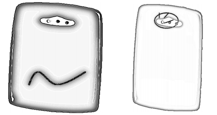
Figure 1 Irregular flow marks Figure 2 After the first improvement
The first improvement is to optimize the two parameters of material temperature and mold temperature. It is found that the flow mark has been improved, but the melting line is more obvious, as shown in the marked area in Figure 2. The second improvement is to further adjust the molding parameters. After the improvement, the defect rate of the product has dropped below 1.0%. The trial production shows that the surface of the product has no flow marks and is flat and smooth.
Table 2 Improvement of molding conditions
| Molding parameters | Original molding conditions | Molding conditions after the first improvement | Molding conditions after the second improvement |
| Injection speed/(mm·s-1) | V1 being 3.5, V2 being 30 and V3 being 280 | The same original molding conditions | V1 being 5, V2 being 100 and V3 being 320 |
| Switch positions/mm | S1 being 24, S2 being 18.5 and S3 being 9.8 | The same original molding conditions | S1 being 24, S2 being 19 and S3 being 9.5 |
| Pressure maintaining/MPa | 80 | The same original molding conditions | 100 |
| Material temperature/℃ | 260, 265, 260 and 255 | 250, 255, 250 and 255 | 250, 255, 255 and 250 |
| Mold temperature/℃ | 80 ℃ for movable molds and 90 ℃ for fixed molds | 70 ℃ for movable molds and 80 ℃ for fixed molds | 80 ℃ for movable molds and 90 ℃ for fixed molds |
| Hot runner temperature/℃ | 230, 230, 258 and 258 | The same original molding conditions | 230, 230, 250 and 250 |

Related News
- Response Strategies for Rapid Prototyping of Metal in the Mechanical Manufacturing
- Applications and Challenges of Rapid Prototyping in Micro-Machining Manufacturing
- Rapid Prototyping of Metals in Mechanical Manufacturing
- Quality Control for the Injection Molding of Automotive Interior Parts
- Solutions to Defects in Injection Molding of Automotive Interior Parts
- The Glossiness of Injection Molded Products
- Painting Injection Molding Parts
- How to Distinguish Various Types of Plastics?
- Characteristics of Plastics
- The Stamping Industry
Services
Advantages
Low Cost
Topper leverages an offshore plastic mold making plant with a lower cost structure in order to offer lower pricing than Topper's competitors.
High Quality
Quick Turnaround
Topper leverages an offshore plastic mold making plant with a lower cost structure in order to offer lower pricing than Topper's competitors.
High Quality
Topper is ISO 9001:2008 certified, and Topper processing quality systems ensure that your parts are the highest quality possible for your applications.
Quick Turnaround
Topper offers three different shipping methods, including next day air, to accommodate your timing and budget requirements.
Online Quotes
Topper interactive online quotation system provides instant quotes for plastic mold making, injection molding, CNC machining and die casting.
Online Quotes
Topper interactive online quotation system provides instant quotes for plastic mold making, injection molding, CNC machining and die casting.
Follow Us
Topper is a professional plastic mold manufacturer in China, our injection molding service covers all walks of life, including medical, electronics, auto parts, appliance, etc.
Contact Us
Topper Plastic Mold Co., Ltd.
Address: No. 879, Xiahe Road, Xiamen, Fujian, China
Tel: 0086-592-5819200
Email: [email protected]
Website: https://www.plastic-mold.com
Copyright © China Plastic Mold Co., Ltd. Robot Arm for Injection Molding. Privacy Policy | Terms of Service | Sitemap
Website Design & Support: jeawin.com